




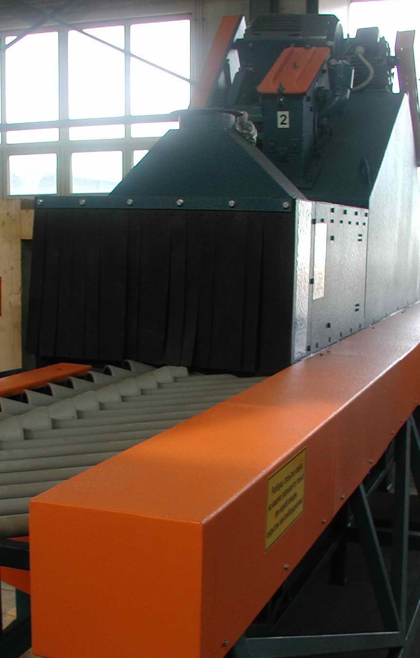
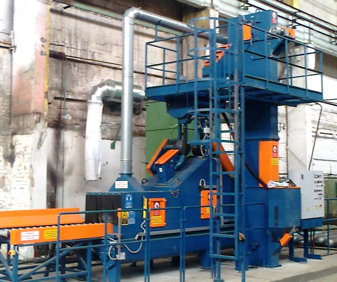
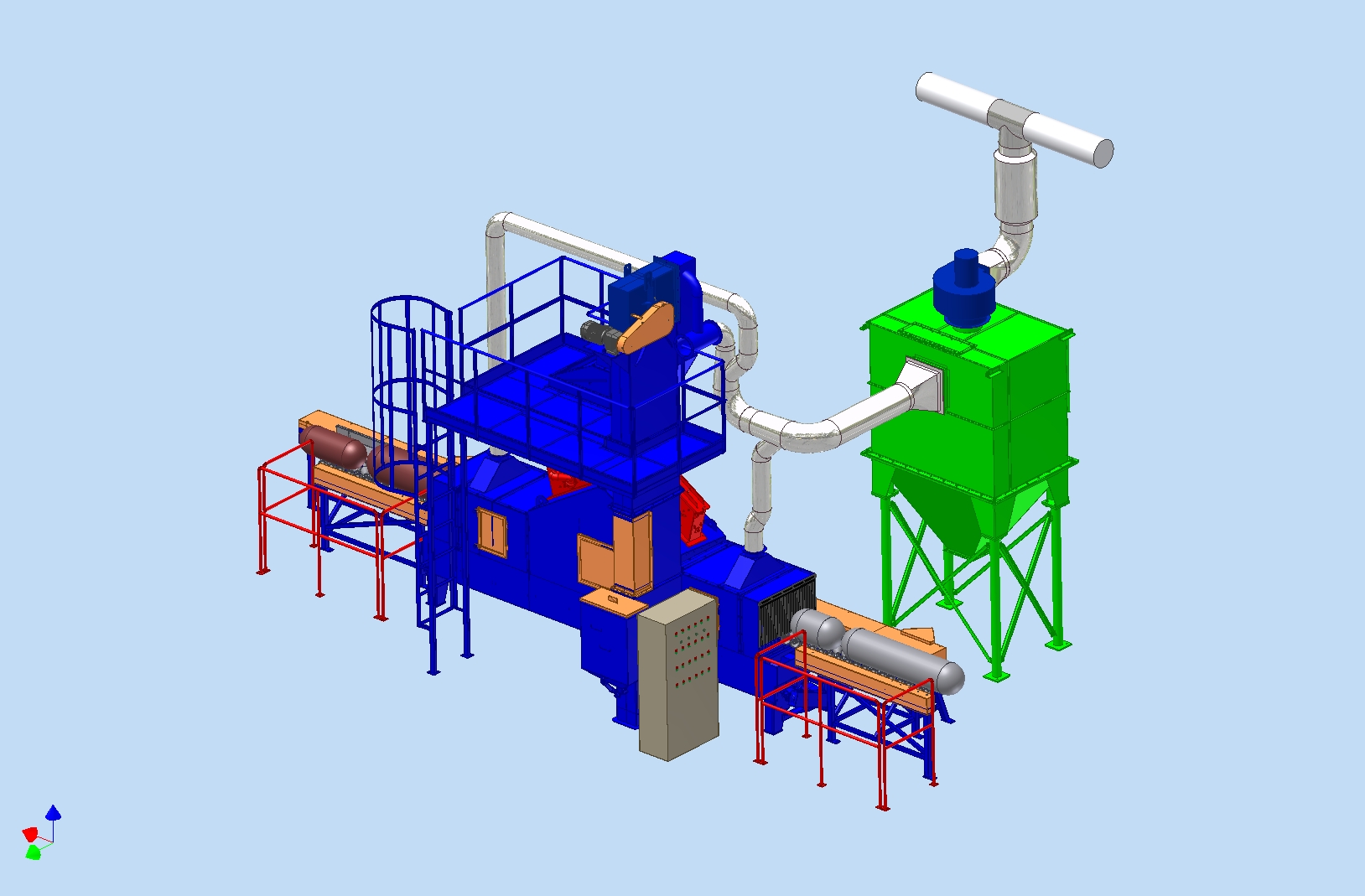
The CST-300 shot blasting machine is primarily designed for the external surfaces of pipes, bottles and cylindrical objects, ongoing suitable for degreasing and surface cleaning. Diameter 100–300 mm. Gas cylinder length: min. 500 mm. Granulate output: 600 kg/min
Durable structural design and standard solutions for safe operation.
Tailored to individual technical requirements, gas types and operating conditions.
The CST-300 shot blasting machine is primarily designed for the external surfaces of pipes, bottles and cylinders, ongoing for its decontamination, surface‐officerításásuitable for.
The CST-300 shot blasting machine is specifically designed for shot blasting the external surfaces of pipes, cylindrical tanks and other cylindrical objects. In this case, we recommend the machine for shot blasting gas cylinders with a diameter of 100–270 mm and a length of up to 1700 mm.
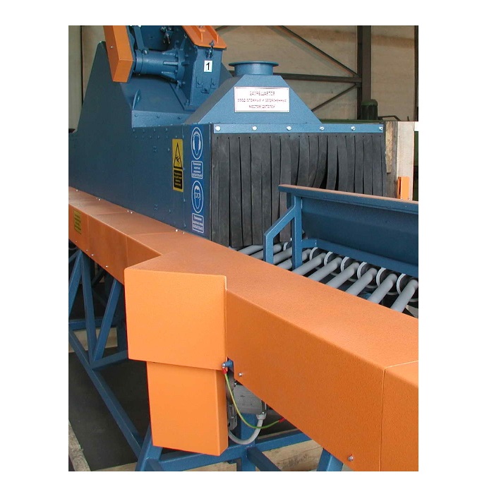
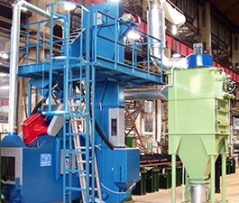
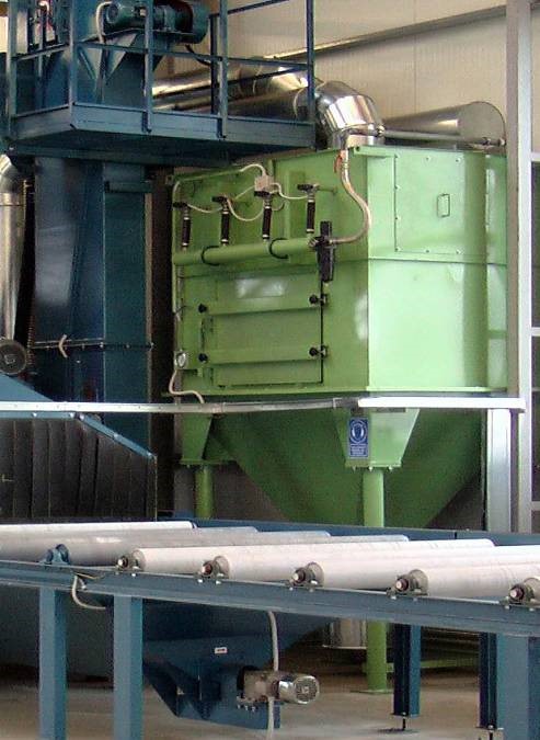
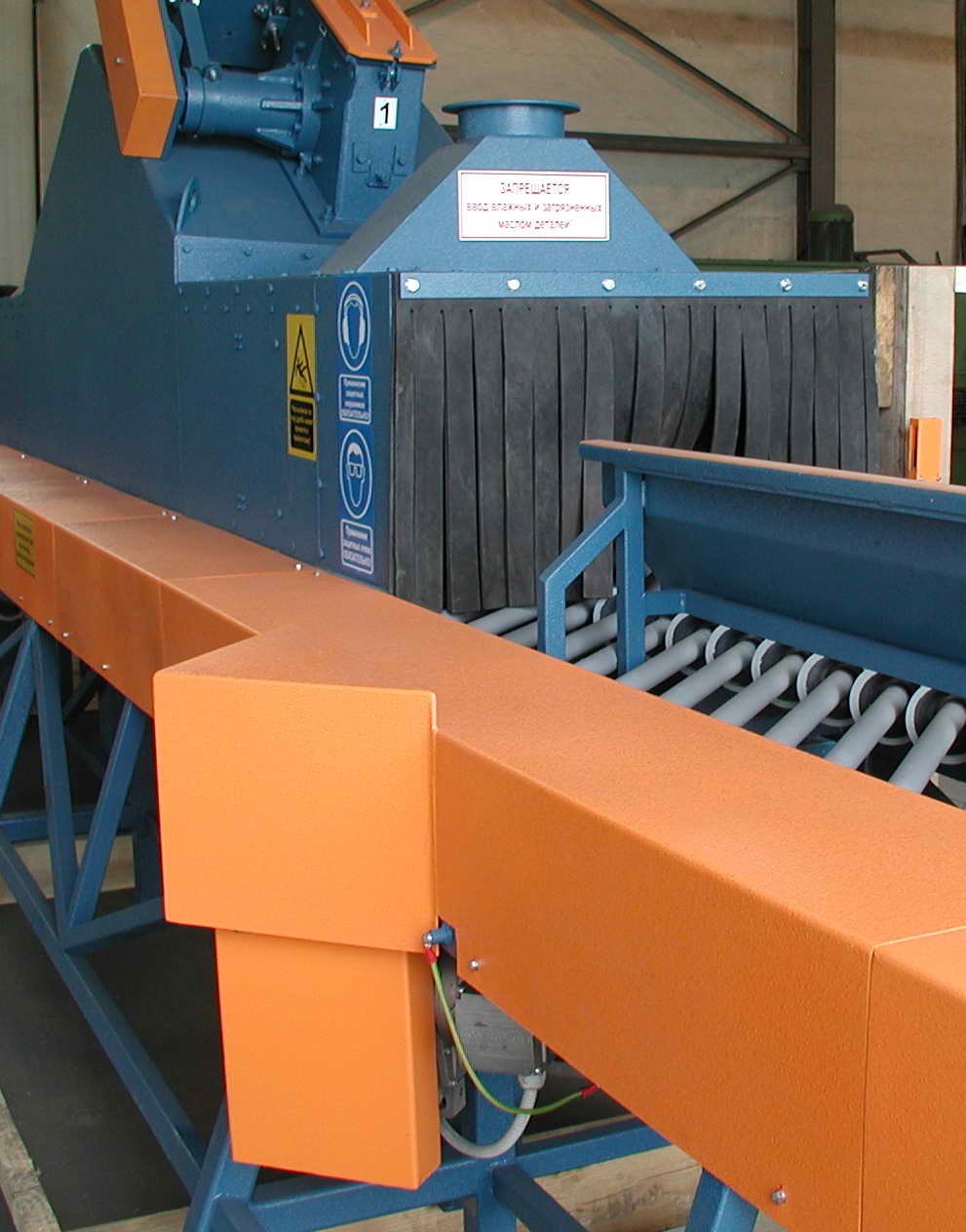
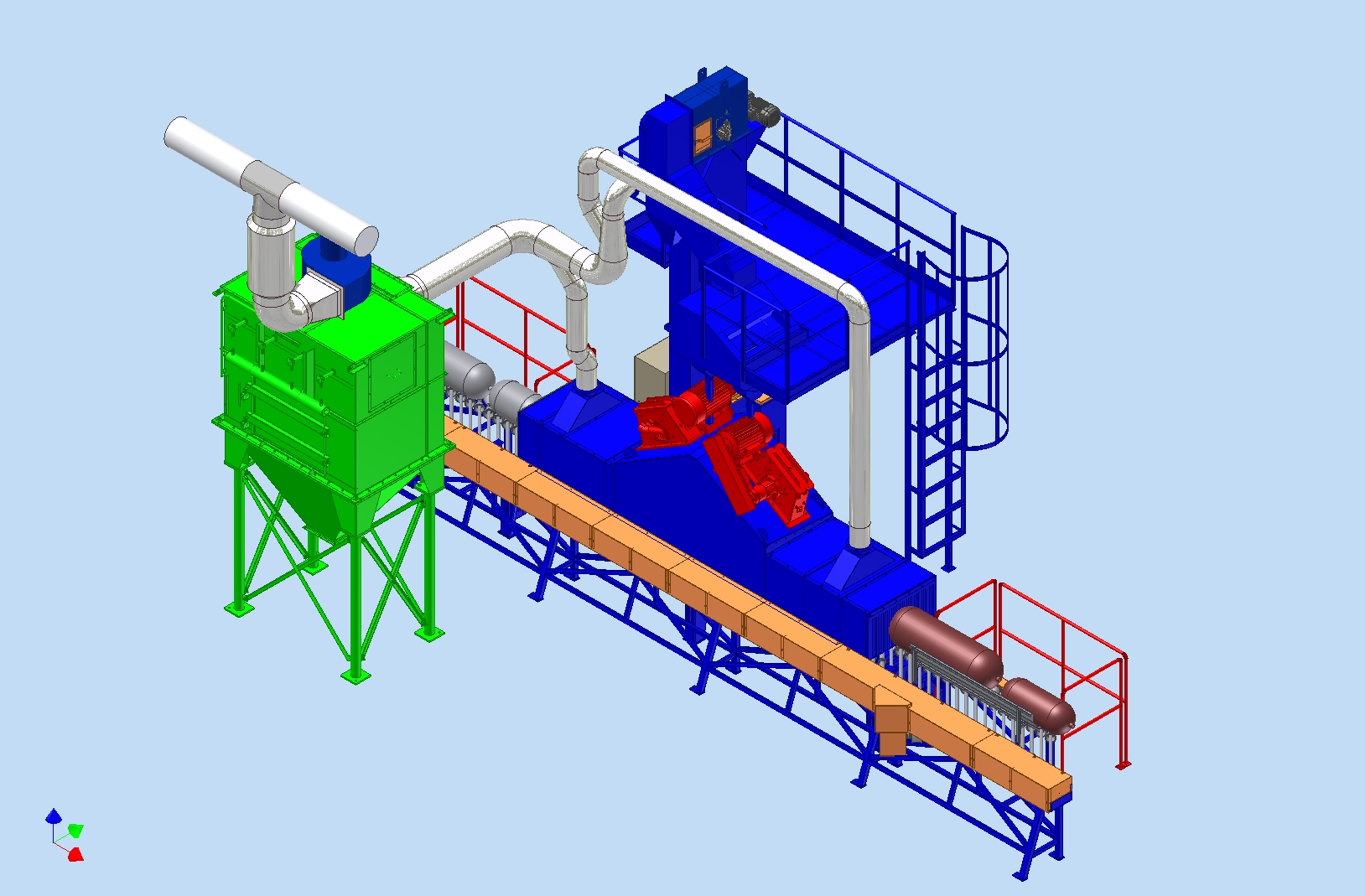
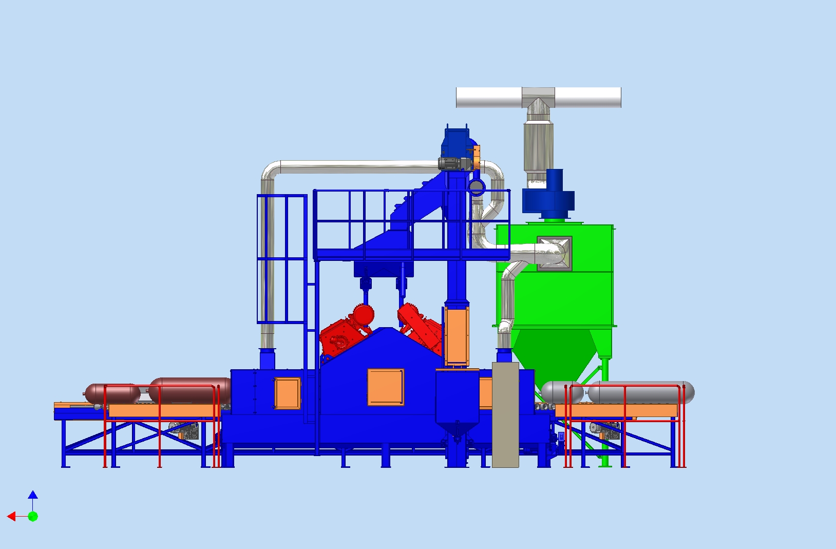
The machine is fitted with two ABR-D 400 spreader heads. The spreader head is positioned above the plane of the roller track. Spreading takes place in a plane parallel to the direction of travel. The spray nozzle is an axial, gravity-fed, eight-blade design fitted with a pre-accelerator, offering precise adjustment of the spray jet. The surfaces of the machine within the active zone are fitted with high-wear-resistant manganese steel linings. Rubber curtains fitted to the machine housing’s inlet and outlet openings prevent the spreading material from escaping. Closed and continuous circulation of the material is ensured by a feed screw, bucket elevator, material cleaning unit and dosing unit. During the cleaning process, the workpiece moves in a straight line whilst simultaneously rotating about its own axis. This is achieved by means of a special diabolical roller track. Every roller on the roller track is driven. The plant’s dust extraction and separation system consists of galvanised steel pipes, moulded components, an extraction fan and a cartridge dust separator. The system’s total extraction requirement is 5000 m³/h at a pressure difference of 2000 Pa. Dust emissions comply with environmental standards. Dust emissions: max. 3 mg/m³. All functions of the machine can be controlled from a central control cabinet. In addition to normal operating mode (automatic operation), manual control is also available for servicing purposes.
The V-belts and chain drives are fitted with covers to prevent access. The access hatches on the machine room are fitted with electric locks to ensure that the machine cannot be started with the door open, and that the equipment stops immediately if the door is opened. The electrical equipment in the control cabinet is secured with a lock to prevent unauthorised operation.
There are four emergency stop buttons on the machine; pressing any one of them will bring the machine to an immediate halt. The machine cannot operate without the dust extraction system running. The airlocks integrated into the machine housing on the inlet and outlet sides prevent the spreading material from escaping. Every unit of the equipment is connected to the wired touch protection system. The power cables are routed to the motors through a protective conduit via a cable gland.
The electrical units of the equipment are provided with the necessary standard markings
The noise level of the grit spreading equipment. The noise generated by the machine is expected to be between 81 and 85 dB(A) when measured in the immediate vicinity of the machine. The noise level generated by the dust extraction and dust separation unit is between 70 and 75 dB(A) following noise insulation and sound attenuation. Higher noise levels than those specified are to be expected during the operation of the valves used to back-clean the cartridges – at which point the impulse noise level is around 80 dB(A). The overall noise level of the equipment can be reduced to below 80 dBA with sound insulation.
Environmental dust pollution. As stated in the tender, the dust concentration in the air downstream of the dust filter is below 3 mg/m³. This is confirmed by the measurements taken to date. The total volume of filtered air can be discharged into the environment or recirculated into the workspace. The dispersant used in the system will be steel grit. Consequently, the airborne particulate matter does not contain fibrogenic substances; in the absence of such substances, the permissible average concentration is 10 mg/m³ in accordance with – MSZ-21461-2:1992, the permissible average concentration is 10 mg/m³.
Manganese wear protection. The entire inner surface of the spreader chamber is lined with a special wear-resistant manganese plate. The manganese plate is 8 mm thick. This wear protection safeguards the machine’s structural components against the damaging abrasive effects of the spreader jet for a long time. Surfaces subject to extra wear and tear are protected by replaceable wear plates made of special alloy steel. The rollers inside the machine housing are also made from a special wear-resistant material. A characteristic property of 13% manganese-containing steel is that its surface becomes increasingly hard due to the impact and abrasion of the grain. (Hadfield steel). Manganese steel is welded using special electrodes that possess wear-resistant properties matching those of the base material.
Engine room. The machine housing is a welded sheet metal structure reinforced with structural steel. The internal surface is fitted with manganese steel wear protection. Two ABR-401 type granule spreader heads are mounted on the side walls of the machine housing in an offset arrangement. The spray nozzles are driven individually by 11 kW electric motors running at 2800 rpm via four V-belts. V-belt tensioning is achieved by tilting the motor mount. The machine housing stands on four legs. Its base is of a conical trough design. This is where fallen granules and heavier contaminants are collected. Inside the conical trough is a conveyor screw, which transports the material to the bucket elevators. The screw shaft is driven by the lower drum of the bucket elevator via a rigid coupling. To extract the dust generated in the machine room, an extraction spigot is fitted to the machine room, through which the machine room is connected to the machine’s complete dust extraction network.
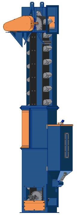
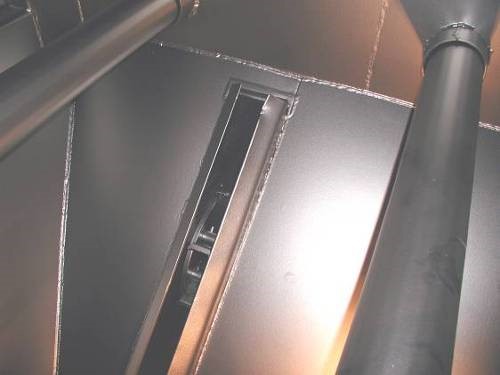
Bucket elevator Main components: lower leg section, upper leg section and the head. The lower leg section incorporates the lower drum of the elevator, which is mounted on bearings on one side of the elevator shaft, whilst the other half is connected to the screw shaft via a coupling. The lower shaft assembly is a welded structure made of bent plate, with connecting frames on the sides for assembly to the worm gear. The upper shaft assembly is a simple self-supporting structure with a rectangular cross-section. This features the mounting hole required for fitting the belt. The head consists of a drum providing the drive for the bucket elevator, a chain tensioning mechanism and a discharge opening. The head is connected to the upper leg by a bolted joint. The drive drum in the head drives the bucket belt, which also serves to tension the belt. The gear motor drives the drum via a chain drive. The buckets are secured to an endless fabric-reinforced rubber belt by means of a screw connection.
A supplementary hopper for the spreading material is fitted to the side of the elevator. The supplementary hopper is connected to the lower section of the elevator via a sliding chute and a pneumatically operated sector valve. The auxiliary hopper feeds extra granules into the system when larger workpieces carry the granules out of the machine room, bridging the downtime until the granules return to the feed hopper. The auxiliary hopper operates fully automatically.
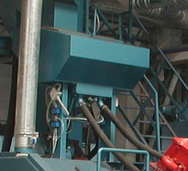
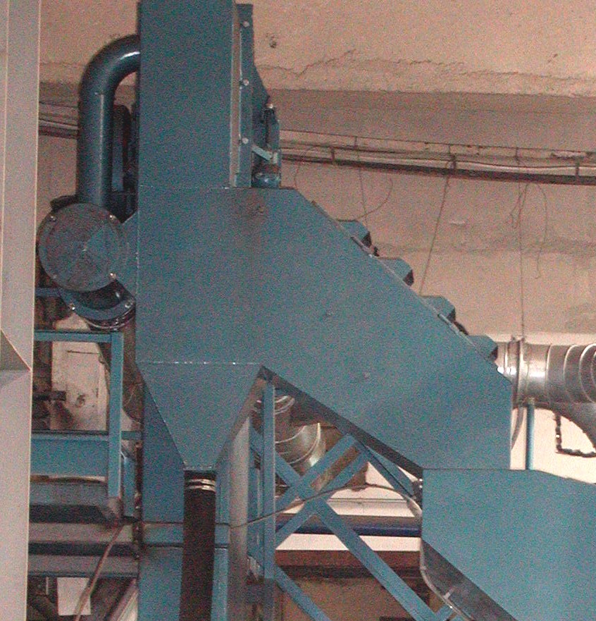
Seed cleaner (wind separator). A two-stage spreader material sorting unit, welded from sheet metal and featuring a suction system. The surfaces of the stages are rubber-coated. Suction openings are located on the door. A pipe stub is fitted to the rear end of the wind sifter. A butterfly valve for regulating air velocity can be connected to either end of this. Dust separated by the air classifier is discharged via a rubber hose into the dust hopper. The cleaned grain flows into the feed hopper.Dispenser tank. The fertiliser sorted by the wind separator is collected in the metering hopper. At the bottom of the metering hopper, sector valves ensure that the correct amount of fertiliser reaches the spreader nozzles. The sector valves are operated by a pneumatic cylinder. The material flowing through the sector valves reaches the spray nozzles via a wear-resistant rubber hose. In the event of the metering hopper becoming overfilled, the excess material is transported via an overflow pipe to the auxiliary hopper on the elevator. The spreading material entering the hopper can only flow through an internal screen, which traps large particles that could cause damage if they reached the spreading head.
Entry and exit gate. Its function is to prevent the spray material from escaping from the machine housing. It consists of multi-layered rubber sleeves and brush segments mounted both horizontally and vertically.
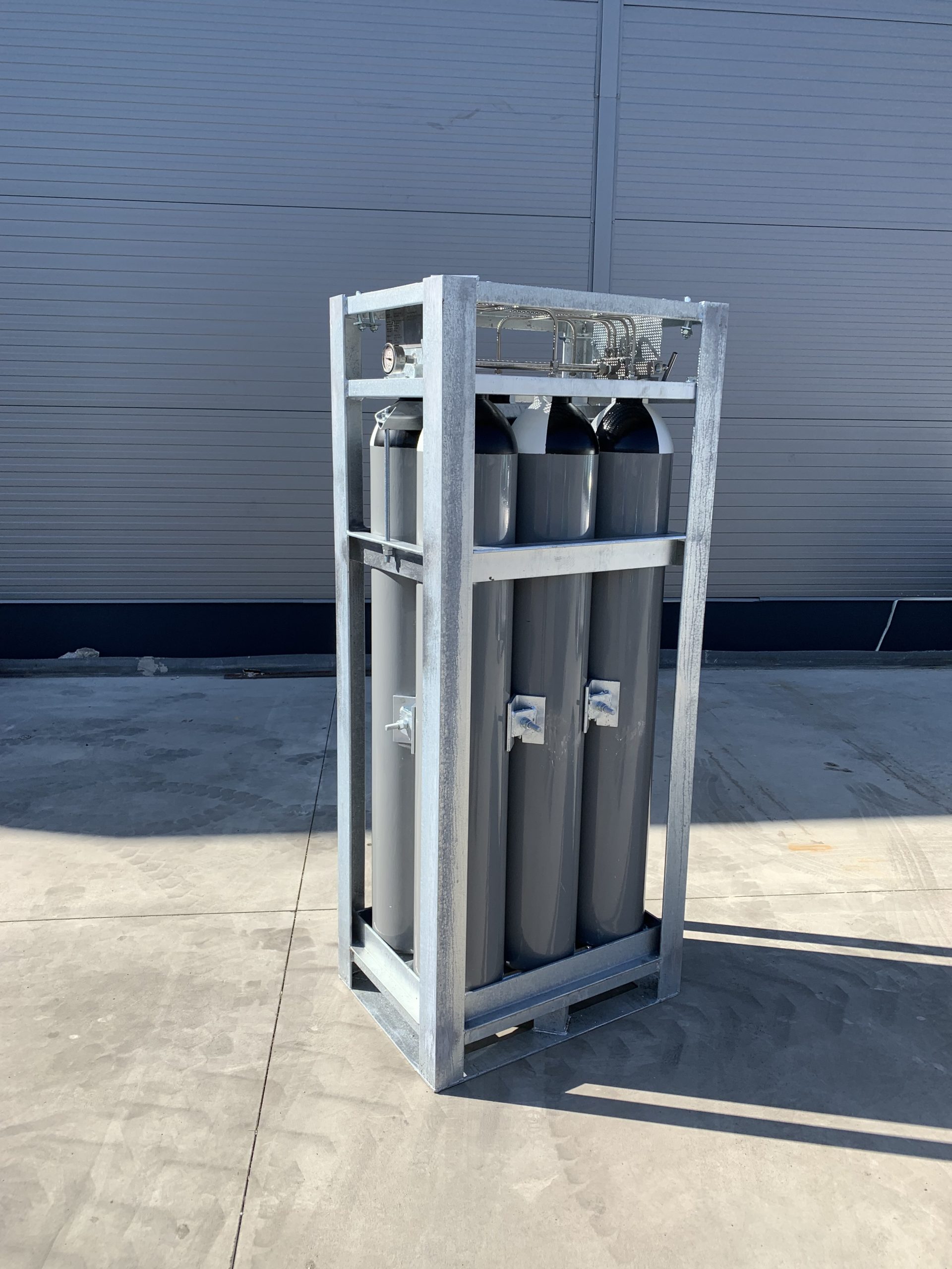
6 x 50 litre gas cylinder bundle for 200 bar, 300 bar or 350 bar operating pressure, for permanent or liquefied gases. Our gas cylinder bundles are manufactured in accordance with EU standards. Welded galvanised structure with stainless steel manifold piping, and many other benefits. Please click for details. For bespoke design and execution, and for volume discounts, please call.
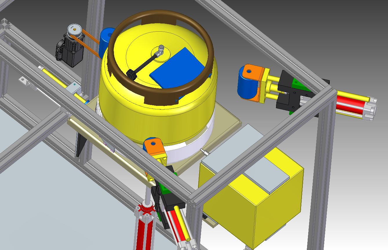
Bespoke labelling and engraving, stamping machine design and manufacture. Whether you have a special bottle size or a special product, we can meet your needs.
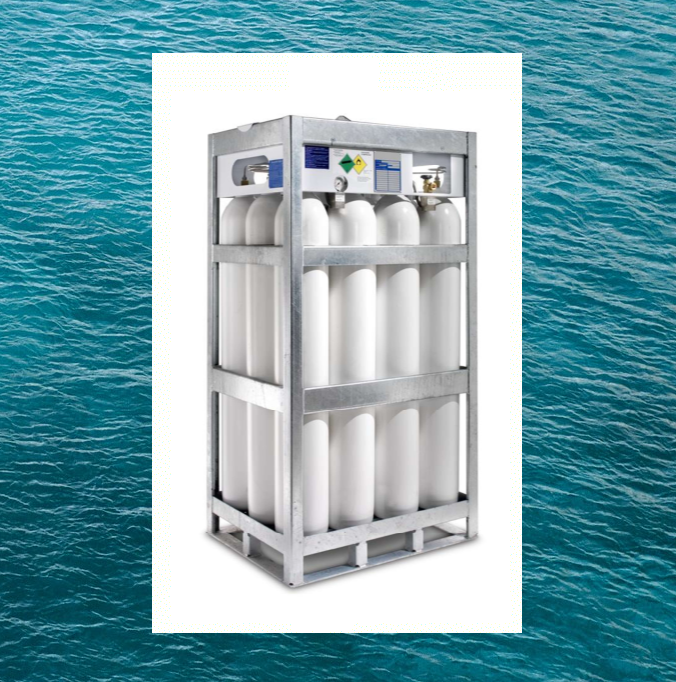
Vertical gas cylinder bundles for marine use. Special fixing lugs, marine-grade surface treatment, approvals for marine and harbour use. Available in 4, 8, 9, 12, 16, 20, 24, 30 cylinder configurations, with operating pressures of either 200 bar or 300 bar. Robot-welded, hot-dip galvanised steel construction. For a bespoke construction and quantity discount, please call us.